|
| |
TM 5-4210-220-34
3-7.
TRANSMISSION-Continued
(35)
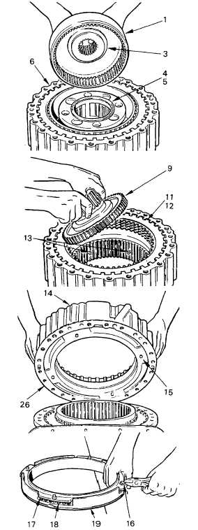
Remove the low ring gear (1) with ball
bearing assembly. Remove the ball
bearing assembly (2) from the ring gear
if bearing replacement is necessary.
(36)
Remove bearing race (3) from ring gear
(37)
Remove the bearing race (4) and needle
bearing (5) from the low planetary carrier
(6).
(38)
Remove
the
low
planetary
carrier
assembly (6). Remove the bearing (7)
and bearing races (8) from the low gear
assembly (9).
(39)
Remove the low planetary carrier (1).
Replace bushing (10) if worn using Tool
J24371. Refer to para. ac. for rebuild of
the low planetary carrier.
(40)
Remove seven external-tanged (11)
and six internal-splined (12) low clutch
plates from the adapter housing.
(41)
Remove 1/8 in. cotter pins from the rear
planetary ring gear (13).
(42)
Remove adapter housing (14).
(43)
Position adapter housing and piston
assembly upward. Lift out the piston
assembly (15).
(44)
Remove the inner (20) and outer (21)
seal rings from the piston.
CAUTION
Any method of removal except cutting may
damage the risers on the piston. Damage will
lessen the holding power of retainer rings
installed thereafter.
(45)
Turn the piston assembly (15) over, and
cut the four retainer rings (16) while
depressing the retainer.
(46)
Remove
the
spring
retainer(17)and
twenty-eight springs (18) from the piston
(19).
(47)
Install new orifice plug (22) flush with
housing. Install new dowel pins (23) if
removed. They must project 0.360-
0.400 in. above the front face of adapter
housing.
3-65
|