|
| |
TM 5-4210-220-34
3-7.
TRANSMISSION-Continued
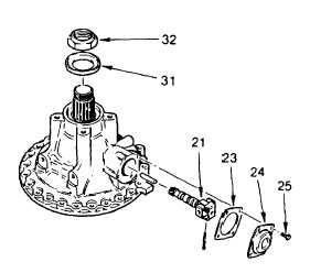
(30)
Coat the outer circumference of dust
shield (31) with seal retainer (item 26,
Appendix B). Install the shield, flat side
first, into the rear cover using installer
J24198. The rear edge of the shield
must be flush with, the rear surface of
the cover.
(31)
Coat the thread of the retaining nut with
grease (item 16, Appendix B). Retain
flange (32) with holder bar. Tighten
flange retaining nut to 600-800 ft lb (814-
1085 Nm).
(32)
Install
the
speedometer
drive
components.
NOTE
Governor assembly may be disassembled for cleaning
and inspection. Do not disassemble the governor unless overhaul kit consisting of governor weight pins and cover gasket
is available.
(33)
Install governor cover gasket (23). Install governor assembly (21) into the rear cover by rotating it
counterclockwise Install cover (24) using four bolts (25) torqued to 13 ft lb (18 Nm). The rear cover is now
ready for final installation.
(34)
Install cover (24) using four bolts (25) torqued to 13 ft lb (18 Nm).
3-64
|