|
| |
TM 5-4210-220-34
3-7.
TRANSMISSION-Continued
(6)
Place carrier rear side up and place all pinion groups into carrier. Install guide pins J25587-49, large
diameter first, in place of loading pins.
(7)
Put carrier on fixture in press. Insert pin installer J25587-9 into fixture ram.
Do not put pressure on the carrier. Distortion of the carrier will damage it.
NOTE
Pin installers are shaped to avoid interference with bosses on the carrier assemblies. They must be
installed in the ram so that the cutaway portion of the installer will clear the bosses when the pinion pin is
pressed in.
(8)
Place a pinion pin (1) onto the pilot end of a pin guide in carrier. Press the pinion pin into the carrier until
the installer contacts the carrier.
(9)
Install the remaining pinion pins.
(10)
Remove the carrier assembly from the press fixture. Install swaging tool holder J25587-17 into the
opening of the press fixture bed. Install a swaging tool J25587-25 into the holder. Install another swaging
tool J25587-25 into the press fixture ram, Lubricate both ends of the pinion pins with petroleum jelly (item
21, Appendix B).
(11)
Position the carrier assembly, rear end
upward on the press fixture. Use
support block J25587-4 to level the
carrier while the lower swaging tool is
supporting the lower end of one pinion
pin.
NOTE
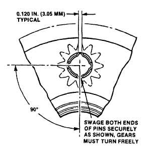
Swaging pressure is approximately three tons for
each pinion pin. While applying pressure, rotate
pinions and feel for reduction of end play. The
pinions must rotate freely and have 0.008 in.
(0.20 mm) minimum end play after swaging the
pins.
(12)
Apply sufficient pressure to the press
fixture ram to firmly swage the ends of
the pinion pins against the metal of the
carriers.
(13)
Swage the remaining pinion pins.
3-54
|

