|
| |
TM 5-4210-220-34
3-7.
TRANSMISSION-Continued
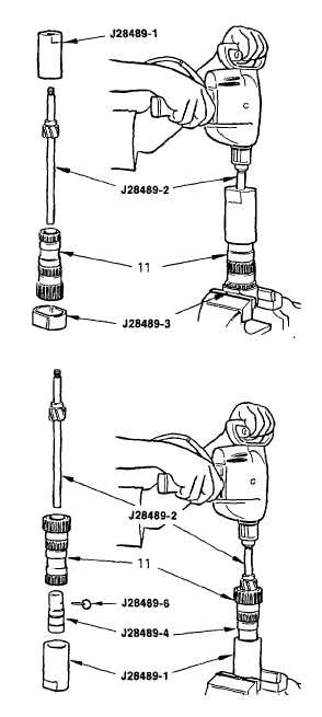
(17)
Using tool J28489, clamp the holding
fixture in a vise. Place the sun gear
shaft assembly in the holding fixture,
and put the reamer and pilot tool in
place.
When machining any bushing, keep reamer at
full drill speed when pulling it back through the
bushing. If reamer is not rotating during
retrieval, it could damage the bushing and
cutting tool.
(18)
Using a 1/2 in. electric drill, machine the
small OD shaft bushing (approximately
75 to 150 rpm) while adding cutting
lubricant (item 8, Appendix B) through
the holes in the pilot tool. If a proper drill
speed
cannot
be
obtained
with
a
standard drill, use a variable speed
control to reduce its rpm.
(19)
To machine the large OD shaft bushing,
clamp the pilot tool in a vise. Insert the
bushing pilot tool J28489-4 into the sun
gear shaft (end with newly machined
bushing) and fasten them together with
the locking pin J28489-6. Using the
same electric drill, engage the shaft of
the reamer in the pilot tool, and machine
the bushing. Add cutting lubricant (item
8,
Appendix
B)
during
machining
operation. Refer to the preceding
caution when retrieving the reamer from
the bushing.
(20)
Check
ID
of
bushings
for
runout.
Runout must not exceed 0.002 in. (0.05
mm) total indicator reading. Surface
finish should be 30 microinch (0.762
micrometer).
(21)
Thoroughly clean shaft of chips and
debris.
(22)
If orifice plug was removed from shaft, use installer J24369 to properly position replacement orifice plug
below chamfer in shaft.
y.
Planetary Carrier Assemblies Inspection And Repair
NOTE
The disassembly and assembly procedures for all planetary carrier assemblies differ only in the proper
tool selection for the specific application and identifies the carrier involved (front, center, rear, low).
3-52
|