|
| |
TM 5-4210-220-34
3-7.
TRANSMISSION-Continued
w.
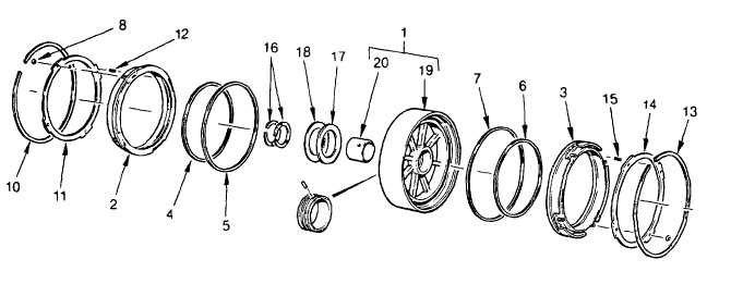
Disassembly And Repair Of Center Support Assembly And Second Clutch
(1)
Place center support housing assembly (1), vertically (upright), on the work table.
(2)
Remove pistons (2 and 3) with attached parts.
(3)
Remove inner seal ring (4 and 6), and outer seal ring (5 and (7) from piston (2 and 3).
(4)
If replacement is necessary, disassemble the two piston assemblies. Cut retainer rings (8 and 9) to prevent
damaging the piston projections.
(5)
Remove the retainer rings (10 and 13), retainers (11 and 14), and springs (12 and 15) from pistons (2 and 3).
(6)
Remove seal rings (16) and discard. Remove thrust bearing race (17) and needle bearing (18) from the hub
of center support housing (19).
(7)
Determine the serviceability of the seal ring grooves on the center support hub. Insert, without force, gage
J29198-3 into a groove on the support hub. Rotate the gage 360 deg. around the hub. If the gage does not
rotate freely, the support is damaged and should be replaced.
NOTE
A damaged or worn center support hub can be salvaged with guidance from the instructions on the
instruction sheet in the Sleeve and Pin Kit. The kit contains one unfinished center support sleeve, and
one sleeve retainer pin and one machining and installation instruction sheet. Kit part number 22011446.
(8)
If bushing replacement is necessary, collapse bushing (20) at its seam using a small half-round chisel. Be
careful not to damage the support bore.
(9)
Place center support (19) on a press, hub side up. Using bushing installer tool J28525-2 (4), install a
prebored bushing (16). Be sure the oil hole in bushing (20) is in proper alinement with the oil hole in
center support (19). Swage bushing using swaging tool J28525-1.
3-48
|