|
| |
TM 5-4210-220-34
3-7.
TRANSMISSION - Continued
(16) Install spring (15) into the converter regulator valve bore. Install converter bypass valve (14) and valve seat
(13).
(17) Install support assembly (11) and snap ring (12) into the valve bore.
(18) Place converter housing on the work table, front side downward.
(19) Place front support gasket (8) onto the converter housing. Aline holes in the gasket with those in the
converter housing.
(20) Install front support assembly onto converter housing.
(21) Install all bolts (16) of proper ;ength in respective holes. Torque bolts to 40 ft lb (52 Nm).
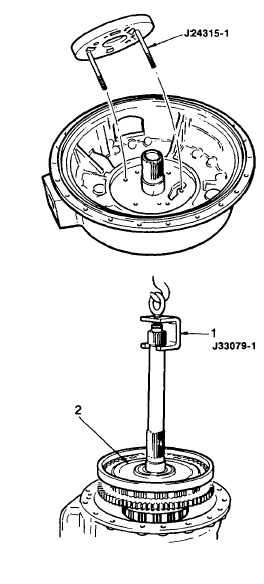
(22) Install two 3/8-16 X 6 in. guide screws J24315-1 into pump as shown.
(23) While holding oil pump in position, install six
bolts. Remove guide pins last. Tighten all
bolts to 43 ft lb (58 Nm).
(24) Lubricate both race and thrust bearings with
petroleum jelly (item 21, Appendix B).
(25) Install bearing race (22) flat side down onto
the front support hub. Install roller bearing
(23) onto the race.
(26) Install both seal rings (24) on support hub.
a.
Removal Forward, Fourth, And Third Clutches
(1)
install lifter tool J33079-1 (1) onto the
forward clutch turbine shaft. Lift out the
forward clutch and turbine shaft assembly
(2).
Do not let weight rest on the governor oil
collector.
(2) During removal of the forward clutch
assembly, do not lose bearing races or
needle bearing, if they adhere to the
forward clutch hub.
(3) Place the hooked legs of lifting tool J24209
under the edges of the fourth clutch spring
retainer (3) and remove the fourth clutch.
3-37
|