|
| |
TM 5-4210-220-34
2-21.
FRONT AXLE - Continued
2-21.2
Differential Carrier - Continued
(16) Press outer pinion bearing (41) onto pinion (34) using a suitable press.
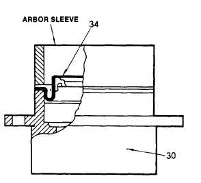
(17) For front axle only, install oil seal (42) in bearing cage (38) using a press or a hammer and a suitable arbor.
Be sure the arbor (sleeve) exerts pressure on seal flange only as shown.
(18) For front axle only, lubricate oil seal with a few drops of oil (Item 15, Appendix B) and install yoke (43),
washer (44), and nut (45). Tighten nut to 700 ft lb (950 Nm) (19)
Carry out final pinion bearing preload
adjustment as detailed in ADJUSTMENT procedure d. following.
NOTE
If ring gear and pinion are to be reused, install same quantity and thickness of shims between pinion
bearing cage and differential carrier as removed. When a new gear set is used, select a nominal shim
pack 0.023 in. (0.58 mm) thick.
(20) Place shim pack (29) on carrier flange. On
front axle differential carrier make sure lube
holes in shims line up with lube holes in
carrier flange.
(21) Install pinion assembly using capscrews
(40) and lockwashers (39). Tighten
capscrews as follows: Front differential, 125
ft lb (170 Nm) Rear differential, 175 ft lb
(235 Nm) (22)
For rear axle, install
helical gear (46) as detailed In procedure c.
following.
(23) Proceed with installation of power divider or
differential carrier to axle as required, see
para. 2-20.1 or para. 2-21.2.
c.
Pinion Helical Gear and Support Bearing Repair
NOTE
This procedure is applicable to rear differential only. If bearing (48) is found faulty when inspected, both
the cone shown as well as the outer race must be replaced, as detailed in para. 2-20.1 REMOVAL
procedure a, step 12 and INSTALLATION procedure a. step 2. If power divider input or output shaft gear,
see para. 2-20.1, or pinion gear (46) Is damaged, all three gears must be replaced.
(1)
Inspect bearing cone (48) and gear (46) as detailed in para. 2-7. If replacement of either component is
required carry out following procedures. If pinion (26) is damaged or faulty, carry out repair as detailed in
REPAIR procedure b. preceding.
(2)
Remove roll pin (51) and nut (49).
2-296
|