|
| |
TM 5-4210-220-34
2-21.
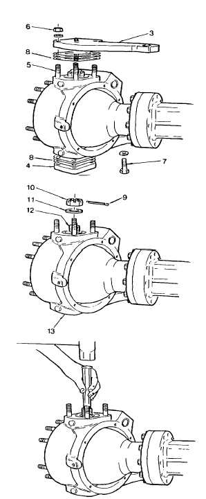
FRONT AXLE - Continued
(2)
Remove kingpin cover (3 and 4). Left top
cover (steering arm) is attached with split-
type dowels (5), lockwashers, and nuts (6).
Right top cover is attached with nuts and
washers (6) only and bottom covers (4) are
attached
with
capscrews
(7)
and
lockwashers.
(3)
Remove
and
identify
shims
(8)
for
installation.
(4)
Remove cotter pin (9), nut (10), and washer
(11) from upper and lower kingpins (12 and
13).
(5)
Using a brass drift (J36136), drive upper
and lower kingpins (12 and 13) out of wheel
end mounts.
(6)
While keeping upper kingpin bearing cone
fully seated in its cup, carefully drive the ball
socket (13) down by striking it with a mallet.
Stop when upper bearing cup is pushed
approximately 1/8 in. (3 mm) above the
bearing cover parting line.
(7)
Repeat step (5) for the lower kingpin
bearing cup.
2-281
|