|
| |
TM 5-4210-220-34
2-20.
REAR AXLE - Continued
REMOVAL
(1)
Loosen power divider input and output yoke nuts (1 and 2) but do not remove. A force in excess of 1000
ft lb (1360 Nm) may be required to loosen nuts.
WARNING
Accidents causing serious or fatal injuries may occur unless the truck is supported on maintenance
trestles. Never rely on hydraulic jacks or mechanical lifting devices for support.
(2)
Lift rear end of truck and place maintenance trestles under the axle.
(3)
Remove differential lock air shift unit (3) as detailed in TM 5-4210-220-12.
(4)
Disconnect air line (4) and remove air shift unit (5) as detailed in TM 5-4210-220-12.
(5)
Remove left and right axle shaft (6) as detailed in TM 5-4210-220-12.
WARNING
Serious injuries may be sustained unless safe work practices are maintained. Do not lie under differential
carrier after attaching hardware is removed. Use a suitable jack to support and remove carrier assembly.
(6) Place a transmission jack under differential carrier and power divider and remove capscrews (7) and nuts
(8).
(7)
Be sure differential lock sliding clutch is engaged, then pull differential carrier (9) free of axle housing
(10).
(8)
Remove power divider (11) from differential carrier (9) as detailed in para. 2-20.1 preceding.
INSTALLATION
NOTE
Before installing differential carrier on
axle housing, inspect and clean interior
of axle housing.
(1)
Install power divider (11) on differential
carrier (9) as detailed in para. 2-20.1
preceding.
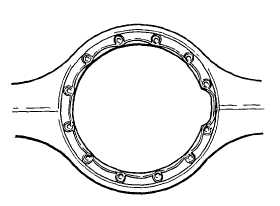
(2) Apply 1/8 in (3 mm) bead silicone
sealant (item 28, Appendix B) to
mounting flange of axle housing as
shown.
(3)
Install differential carrier (9) in axle
housing
(10)
using
lockwashers,
capscrews (7), and nuts (8). Tighten
capscrews to 220 ft lb (300 Nm) and
nuts to 240 ft lb (325 Nm).
2-277
|

