|
| |
TM 5-4210-220-34
2-20.
REAR AXLE - Continued
(5)
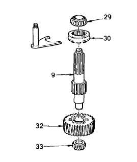
Lift and remove output shaft (9) and shift
fork (10) from power divider.
NOTE
Before
disassembling
output
shaft
components
clean
and
inspect
the
assembled
components.
Unless
replacement of one or more parts is
required, the output shaft should be left
assembled for reuse. For disassembly,
refer to steps 6 and 7 following.
To prevent damage to clutch teeth use a
suitable sleeve or collar to support gear
(32) while pressing shaft (9).
(6)
To
replace
output
shaft
components,
remove bearing cones (29 and 33) from
output shaft (9). Sliding clutch (30) will slide
off shaft when cone (29) or cone (33) and
gear (32) is removed. Use a split type
puller to remove cone (29) from shaft. Use
a press to remove cone (33) and gear (32).
NOTE
If bearing (33) has to be replaced, remove bearing cup from power divider cover, see procedure b, step 11
following.
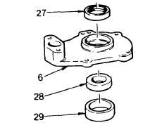
(7)
Remove oil seal (27) and discard.
Retain spacer (28) and, if necessary,
remove bearing cup (29) from bearing
cover (6) using a press and suitable
arbor.
2-267
|