|
| |
TM 5-4210-220-34
2-19.
ENGINE - Continued
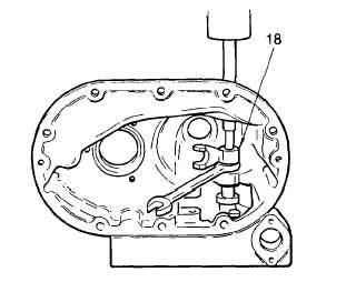
(12) With the housing still supported on the
press, place a 9/16 in. wrench under
the operating fork as shown.
(13) Place a brass rod on the end of the
shaft and press the fork (18) off the
operating shaft.
(14) Remove the shaft (17), operating lever
(11) and bearing (15) as an assembly
from the housing.
(15) Using a suitable puller, withdraw the
lower bearing (20) from the bottom of
the housing.
(16) Slide the operating shaft spacer (16)
from the shaft (17).
(17) Place a short 9/16 in. inside diameter sleeve over the end of the operating shaft (17) and rest it against
the inner race of the upper bearing (15).
(18) Support the operating shaft (17), lever (11), bearing (15) and sleeve on a large washer or plate (with a
5/8 in. hole) on the bed of an arbor press.
(19) Place a small brass rod on the end of the shaft and press the operating shaft (17) out of the lever (11)
and bearing (15). Be sure the bearing inner race is resting on the sleeve or the bearing may be
damaged.
(20) Inspect the control link operating lever (29) for wear or damage to the needle bearings (28 and 35). If
damaged, press out using tool J8985 in an arbor press. Support the lower end of the lever on a sleeve
which is the same size as the boss on the lever.
(21) Inspect all parts for excessive wear or damage. Replace components as required. For bearing
inspection, see para. 2-7.
(22) Lubricate the inside diameter of the upper bearing (15) with engine oil (item 17, Appendix B).
(23) Start the bearing, number side up, on the large end of the operating shaft (17).
(24) Support the bearing and shaft on a 9/16 in. inside diameter sleeve on the bed of a press. With the
inside diameter of the bearing resting on the sleeve, press the shaft into the bearing until 1/4 in. (6 mm)
of the shaft protrudes through the bearing.
(25) Lubricate the inside diameter of the operating shaft lever (11) with engine oil (item 17, Appendix B).
Start the lever, pivot pin (10) facing up, on the shaft (17) , the flat on shaft and lever keyed together.
(26) Continue to press lever (11) against the bearing (15) and onto shaft (17) until the shaft is flush with the
top opening of the lever.
(27) Place spacer (16) over shaft (17).
2-261
|