|
| |
TM 5-4210-220-34
2-19.
ENGINE - Continued
INSPECTION
(1) Inspect winterization valve block on water pump housing and inspect the valves. Check seats are clean and
valves operate smoothly. Replace any valves failing inspection.
(2) If a new water pump is to be installed,
remove valve block from old housing and
install on new housing. Coat threads with
pipe sealant (item 22, Appendix B) prior to
installation.
(3) Mount pump drive gear in a soft jawed vise.
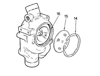
(4) Using snap ring pliers, remove snap ring
(14).
(5) Lift off pump cover (15). Do not remove
seal ring (16).
(6) Remove water pump from vise and rotate impeller by hand. Check for any looseness in the bearing. Repair
as required. See REPAIR following.
(7) If required, check impeller for build up of contaminants or foreign material. Remove impeller and repair as
detailed in REPAIR following.
INSTALLATION
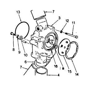
(1) Install seal ring (13) on pump body. Use grease (item 16, Appendix B) to hold in position.
(2) Mount pump on the engine. Be sure pump meshes
with front right-hand camshaft gear and dowel pin
engages in front engine plate hole.
(3) Install and tighten mounting bolts (11) and
washers (1 2).
(4) Install and tighten mounting bolt (8), washer (10),
and lockwasher (9).
(5)
Install a bolt in the impeller puller holes (B) and
measure the backlash with a dial indicator. Rear
backlash should be 0.001 0.006 in. (0.025 0.15
mm).
(6) Adjust backlash to these limits by loosening bolts (8 and 11) and pivoting pump either clockwise or
counterclockwise.
(7) Retighten mounting bolts to 50 ft lb (68 Nm).
(8) Install pump cover (15) on water pump housing. Be careful not to damage front seal ring (16) in housing.
2-221
|