|
| |
TM 5-4210-220-34
2-19.
ENGINE - Continued
b.
Exhaust Valve Bridge Guide Repair
NOTE
The valve bridge guide cannot be
repaired, replace as detailed following.
If
the
guide
is
broken
refer
to
instructions 6 thru 9 following.
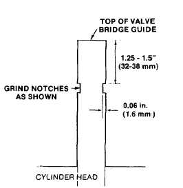
(1) File or grind two diametrically opposite
notches 0.06 in. (1.6 mm) deep in the side
of the guide approximately 1.25 1.5 in. (32
38 mm) from the upper end.
(2)
Place spacer J7091-3 over the guide.
(3) Slide guide remover J7091-5 over the guide and aline the set screws with the notches in the
guide. Tighten the set screws firmly.
(4) Place spacer J7091-4 over the guide remover and thread the nut on the remover.
Turn it
clockwise to withdraw the guide from the head.
(5) For installation of a valve bridge guide refer to step 10 following.
(6) To remove a broken exhaust valve bridge guide, drill a hole approximately 0.5 in.
(13 mm) deep in the
end of the guide with a # 3, 0.213 in.
(5.41 mm) drill bit.
(7) Tap the guide with 1/4 in. - 28 bottoming tap.
(8) Thread remover J7453 into the guide and attach slide hammer J2619-01 to the tool.
(9) One or two sharp blows with the puller weight will remove the broken guide.
(10) Apply retaining compound (item 23, Appendix B) to the undercut end of the new valve bridge guide.
(11) Start the guide straight into the cylinder head.
(12) Place installer J7482 over the guide and drive it into place.
The installer will properly position the guide to
the correct height in the cylinder head.
c.
Valve Seat Insert Repair
(1) Turn cylinder head bottom side up and support on wooden blocks.
(2) Use the cam operated valve insert puller J23479-35 and collet J23479-33 to remove the insert from the head.
(3) Clean the valve insert counter bore and the new valve seat insert.
2-211
|