|
| |
TM 5-4210-220-34
2-19.
ENGINE - Continued
(19) Turn the idle speed adjusting screw in until it project
3/16 in. (4.8 mm ) from the locknut.
(20) Place the governor stop lever in the run position and
the speed control lever in the idle position.
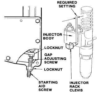
(21) Adjust the starting aid screw until the gage J23190
exactly fits the gap
(22) Retighten starting aid screw locknut.
(23) Recheck the gap after moving speed control lever to
maximum speed and back to idle a few times.
Adjust starting aid screw as required.
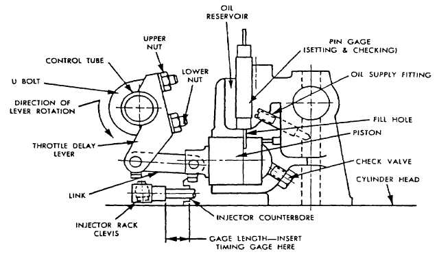
(24) Fill the throttle delay reservoir (detent in top of
mechanism) with engine oil (item 17, Appendix B).
(25) Insert the rack gage J25560 on the rack between No. 2R injector body and the shoulder on the injector rack
clevis.
(26) Hold the governor throttle lever in the maximum position.
(27) Insert pin gage J25558 with the green 0.069 in. (1.75 mm) end in the cylinder fill hole as shown. Use the
hole to the rear of the engine.
(28) Rotate the throttle delay lever in the direction shown until further movement is limited by the piston contacting
the gage.
2-197
|