|
| |
TM 5-4210-220-34
2-19.
ENGINE - Continued
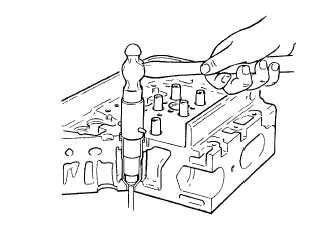
(8) Place installer J5286-4B in new injector
tube. Insert the pilot J5286-5 through the
small opening of the injector tube. Thread
pilot onto installer and handtighten.
(9) Slip injector tube and installer assembly into
cylinder head. Drive carefully into place.
The injector tube upper flange is used to
retain seal. The seal
is accomplished
between
head
counterbore
(inner
diameter)
and outside diameter of tube.
(10) Turn cylinder head upside down. Remove
pilot J5286-5.
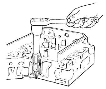
(11) Thread flaring dye J5286-6 onto tapped end
of installer J5286-4B.
(12) Using socket and torque wrench apply 30 ft
lb (41 Nm) torque to the flaring dye.
(13) Remove all tools from injector tube.
(14) Turn cylinder head right side up and clean
injector tube.
(15) Place a few drops of cutting oil (item 8,
Appendix B) on reamer J22525-1. Insert
reamer carefully into injector tube.
(16) Turn the reamer clockwise. Withdraw every
2 turns to remove chips. Keep cutting until
shoulder of reamer contacts the Injector
tube. Withdraw reamer and clean injector
tube.
(17) Turn cylinder head upside down and place
a few drops of cutting oil (item 8, Appendix
B) on cutting tool J5286-8. Insert carefully
into small hole of injector tube.
(18) Remove excess stock from lower end of tube so tube is flush to 0.005 in. (0.13 mm) below the finished
surface of the cylinder head Withdraw cutting tool J5886-8. Clean injector tube.
(19) Insert gage tool J25521 into injector tube. Zero the sled dial indicator J22273 on lower face of cylinder head.
(20) Slide sled dial indicator so its pointer contacts the gage tool. Hold gage tool firmly in injector tube. Dial
should read 0 + 0.014 in. (0 + 0.36 mm).
(21) Place a few drops of cutting oil on the bevel seat of the tube Carefully lower reamer J5286-9 into injector tube
until it contacts the bevel seat.
2-191
|