|
| |
TM 5-4210-220-34
2-19.
ENGINE - Continued
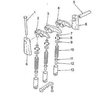
(4)
Assemble the serrated lower spring seat (11), spring (10), and upper spring seat (9), on the push rod
(12).
(5)
Place a flat washer over the upper spring seat and start the locknut (7) on the push rod. Place tool
J3092-02 on the push rod between the washer and the upper spring seat and place the push rod
assembly in the cam follower (13).
(6)
Thread the locknut (7) on the push rod until the spring Is compressed sufficiently to permit the spring
retainer (8) to be installed.
(7)
Install the retainer (8) with the tangs facing the notch in the cylinder head.
(8)
Remove the nut, flat washer, and tool. Then reinstall the locknut (7) and thread It as far as possible on
the push rod (12).
(9)
The injector rocker arm (3) is slightly different from the exhaust valve rocker arms (2 and 4), the boss for
the shaft on the left and right-hand valve rocker arms is longer on one side. The extended boss of
each valve rocker arm must face toward the
injector rocker arm. The exhaust valve rocker
arms also have a flat spot beneath the rocker
shaft hole to ensure clearance with the valve
bridge
NOTE
If the rocker arm is damaged or breaks, the push
rod should always be changed when the new
rocker arm is installed.
(10) Thread each rocker arm on its push rod (12)
until the end of the push rod Is flush with or
above the inner side of the clevis yoke This will
provide sufficient initial clearance between the
exhaust valve and the piston when the
crankshaft is turned during the valve clearance
adjustment procedure
(11) If removed, install cylinder head on the engine,
see para. 2-19.8.
(12) Lubricate the valve bridge guides with gear oil (item 15, Appendix B) and position the valve bridges in
place on the guides. Refer to para. 2-19.7 and adjust the valve bridges.
(13) If removed, install the fuel injectors. See para. 2-19.5
(14) Apply clean engine oil (item 17, Appendix B) to the rocker arm shaft (5) and slide the shaft through the
rocker arms. Then place a bracket (6) over each end of the shaft with the finished face of the bracket
next to the rocker arm.
(15) Insert the rocker arm bracket bolts (1) through the brackets (6) and the shaft (5). Tighten the bolts to 90
ft lb (122 Nm).
2-177
|