|
| |
TM 5-4210-220-34
2-19.
ENGINE - Continued
2-19.4
Rocker Arms, Cam Follower, And Push Rods - Continued
(5)
Inspect the rocker arm shaft brackets for cracks.
(6)
Examine the cam follower rollers for scoring,
pitting or flat spots. The rollers must turn freely on
their pins.
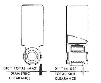
(7)
Measure diametric clearance and side clearance
as shown. Replace roller and pin if clearances
are exceeded (see REPAIR following).
(8)
Examine the camshaft lobes for scoring, pitting or
flat spots. If camshaft requires repair, refer to
General Support.
(9)
Measure the cam follower bores in the cylinder
head with a telescope gage and micrometer and
record the readings.
(10) Measure the diameter of the cam followers with a micrometer. Record the readings and compare the
readings of the followers and bores to determine the cam follower-to-bore clearances. Maximum
clearance should be 0.005 in. (0.13 mm).
(11) If the push rod is broken or damaged, the rocker arm should be suspect. Any wear or excessive
movement in the rocker arm or clevis can put a side load on the push rod, resulting in fracture or
damage.
(12) Inspect the rocker arm for signs of wear or cracking. If wear or excessive movement of the rocker arm
or clevis is noted, replace the rocker arm.
(13) Inspect the push rods and spring seats for wear. The push rods have milled wrench flats and a bright
"turned" finish and the lower spring seats are serrated along the push rod contact surfaces.
(14) Examine the cam follower springs for wear or damage and check the spring load. Replace a spring
when a load of less than 250 lb (113 kg) will compress it to a length of 2.1406 in. (54.371 mm). Use
spring tester J22738-02 to check the spring load.
INSTALLATION
(1)
Before cam followers are installed, immerse
them in clean engine oil (item 17, Appendix B)
heated to 100 - 125 deg. F (38 - 52 deg. C)
for at least one hour. Rotate rollers regularly
to ensure bushing is purged of air.
(2)
Install cam followers and push rods in their
original locations as noted in REMOVAL
preceding.
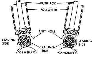
(3) Note the oil hole In the bottom of the cam the
follower. With the oil hole directed away from exhaust valves, slide the cam follower in position in the
cylinder head.
2-176
|