|
| |
TM 5-4210-220-12
4-32. FRONT AXLE - Continued
ADJUSTMENT
(1) Block the rear wheels to prevent the truck
from moving while working on the front
axle.
(2) Jack affected wheel end up as detailed in
para. 4-9. Support raised wheel end on
maintenance trestle.
NOTE
Brake adjustment may be carried
out
with
front
wheel
either
removed or installed.
(3) Connect truck batteries and start engine.
Run engine until air system is at normal
pressure.
(4) Stop the engine and disconnect truck
batteries.
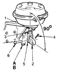
(5) Push locking sleeve (B) on slack adjuster
down
and
turn
adjustment
screw
(A)
clockwise until brake shoes are tight against
brake drum.
(6) Back off screw (A) approximately two turns,
10-12 flats on the screw head, until there is
no brake drag.
(7) Be sure locking sleeve (B) engages adjuster
screw (A) when adjustment is completed.
(8) To be sure brakes are free and without drag,
tap brake drum with a hammer and listen for
a clear ringing sound, or turn the wheel in
forward and reverse direction and check
that brake shoes do not rub against brake
drum.
(9) Apply the brakes using the brake pedal in
the cab. Check the angle between air
chamber push rod (1) and slack adjuster
(2) as shown. The angle should be 90 deg.
(10) To adjust position of clevis, loosen jam nut
(3).
(11) Remove cotter pin (4) and disconnect
clevis (5) from slack adjuster by removing
pin (6).
(12) Turn clevis (5) as required to increase or
decrease overall length of push rod.
(13) Connect clevis (5) to slack adjuster (2) and
install clevis pin (6). Secure clevis pin
using cotter pin (4).
(14) Tighten jam nut (3) against clevis.
(15) Recheck angle between slack adjuster and
push rod as detailed in step 9 above.
(16) Repeat steps 2 thru 15 on second front
brake.
4-603
|