|
| |
TM 5-4210-220-12
4-25 STEERING SYSTEM - Continued
WARNING
The pitman arm can work loose
and result in loss of vehicle
steering control unless the arm is
installed and secured as detailed
in steps 5 thru 8.
(5)
Install and tighten nut (3) to approximately
450 ft lb (610 Nm).
(6)
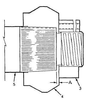
Remove nut (3). Measure distance A
between pitman arm and shaft shoulder
as shown. Distance A should be 1/8 to
3/32 in. (3 to 4 mm). If less than 1/8 in. (3
mm), replace output shaft as detailed in b.
following.
(7)
Install nut (3) and tighten to 675 ft lb (915
Nm).
(8)
Install lockwasher (2) and capscrew (1).
Tighten capscrew to 15 ft lb (20 Nm).
b.
Output Shaft Repair.
NOTE
Steering gear removed from truck.
WARNING
To prevent a serious accident, do
not weld or apply excessive heat
to pitman arm or output shaft.
Welding or excessive heat may
lead to component failure and
loss of steering control.
(1)
Remove pitman arm as detailed in a
preceding.
(2)
Remove screws (1) and washers (2)
attaching cover (3).
(3)
Using a soft hammer, tap on end of output shaft to loosen cover.
(4)
Carefully slide output shaft, pinion gear, and cover through housing. Pull output shaft (4) out of cover (3)
and discard O-ring (5).
(5)
Inspect bearings (6 and 10) while these are still installed in gear housing (12) and cover (3). The bearings
should remain installed unless damaged or defective.
(6)
If replacement of either bearing is required, use a suitable internal bearing puller to remove the defective
bearing.
4-491
|