|
| |
TM 5-4210-220-12
1-19. FIREFIGHTING SYSTEM. - Continued
e. Water and Form Control - CFR Mode.
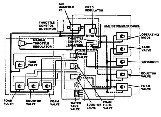
(1) With the mode switch selected to CFR, manifold #2 is isolated and air flow is provided to the TANK VALVE
switch, (see fig. 1-39). When the TANK VALVE switch is set on OPEN, air pressure is provided to open the tank valve.
(2) When the PUMP switch is set to ON (see para 1-19c.), air flow is also provided via the energized solenoid
valve (L) to the GOVERNOR switch. Setting this switch to ON provides air flow to the throttle control governor. The air
flow is regulated to 80 psig by the fixed regulator. Refer to paragraph 1-13 for details of throttle operation. Control air
flow is also provided to the FOAM VALVE and WATER EDUCTOR switches.
Figure 1-39. Water and Foam Control - CFR Mode.
Change 6 1-46
|