|
| |
TM 5-4210-220-12
4-25. STEERING SYSTEM - Continued
4-25.5 Drag Link
This task covers
a.
Adjustment
b.
Replacement
c.
Repair
TOOLS
Tool Kit, General Mechanic, Automotive,
NSN 5180-00-177-7033
EQUIPMENT CONDITION
Main Engine Shutdown (see para. 2-10)
APU Engine Shutdown (see para. 2-12)
Battery Switch OFF
Steering Shaft Covers Removed
MATERIALS/PARTS
16, Appendix E Grease
HL-25709-H Drag Link
1/4 x 3 Cotter Pin
221589 Dust Shield
PERSONNEL REQUIRED - 2
ADJUSTMENT
NOTE
Front wheel alinement must be checked and
adjusted prior to adjusting drag link, see
para. 4-32.2.
(1)
Position truck front wheels straight ahead.
(2)
Be sure there is no noticeable play between link end
(6) and pitman arm ball. If excessive play is
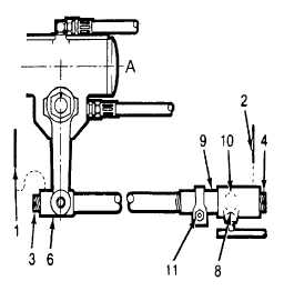
observed, remove cotter pin (1) and tighten plug (3)
until it bottoms against ball, then back off until cotter
pin (1) can be installed install and secure cotter pin.
(3)
Note position of pitman arm relative to steering gear to
determine if adjustment of drag link is necessary, i.e.,
whether to increase or decrease length of drag link.
When drag link is correctly adjusted the pitman arm
should be at right angles to the steering gear axis (A)
when the wheels are straight ahead.
(4)
Remove cotter pin (2), plug (4) and loosen dust shield (8). Remove link end (9) from axle linkage ball
(10).
(5)
Loosen nut (11) and turn link end (9) clockwise or counterclockwise (full turns) to adjust length of drag
link.
NOTE
One full turn of link end (9) changes the length of the link approximately 3/32 in. (2 mm).
Three full turns changes the length 1/4 in. (6.4 mm).
4-484
|