|
| |
TM 5-4210-220-12
1-19. FIREFIGHTING SYSTEM. - Continued
b. Foam Induction System.
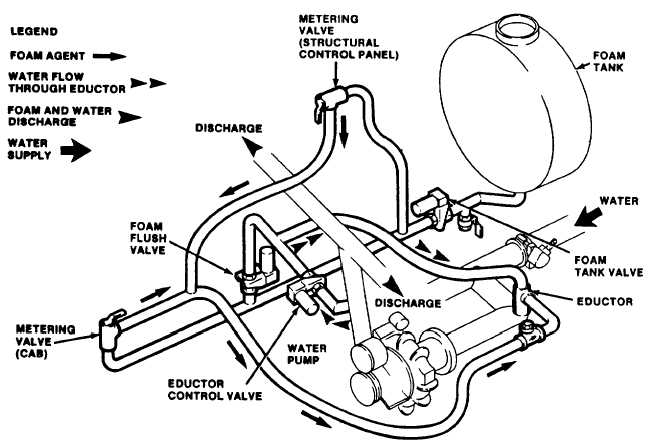
(1) Foam concentrate is released from the foam tank and metered into the water flow to the pump, (see fig. 1-37).
In CFR mode, the control valves through which the concentrate is released and metered are operated from the cab. In
structural mode, these functions are controlled from the structural control panel. To produce foam, water (derived from
the pump discharge) is cycled through the eductor into the pump suction. In the eductor, the water draws the foam
concentrate into the flow by venturi action.
(2) To remove residual foam from the foam lines after firefighting, the foam tank valve is closed and the flush valve
is opened. Water from the pump discharge is then cycled through the metering valves and through the eductor.
Figure 1-37. Foam Induction System
c. Pump and System Interlock Control - CFR Mode.
(1) When the tank valve is opened in CFR mode, the switch (A), located on the tank valve, closes. This action
causes the TANK VALVE OPEN indicator to illuminate and also enables the circuit to the pump switch, (see fig. 1-38).
(2) When the pump is switched ON, the PTO solenoid valve is energized. This allows pressurized oil from the
transmission to engage the PTO clutch. The oil pressure also triggers the oil pressure switch causing the PUMP
ENGAGED indicator to illuminate and the throttle control solenoid valve (L) to energize The pressure switch (C) remains
closed since no air pressure is applied to manifold # 2 in CFR mode, (see para. 1-19 e.)
1-44
|