|
| |
TM 5-4210-220-12
4-24. ELECTRICAL SYSTEM - Continued
g.
Voltage Regulator Adjustment
(1)
Set battery switches to BOTH and start main engine as detailed in Chapter 2.
(2)
Run the engine at approximately 1500 rpm and switch on the headlights. Because of the short duration of
this test, adjust engine speed with the foot throttle. Keep at steady 1500 rpm.
(3)
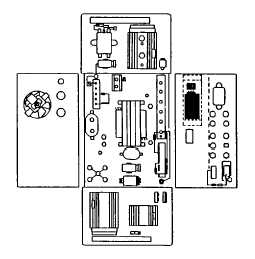
Connect the 4-2700 test strip to the front of the inverter and measure the voltage black to green.
(4)
Voltage should be between 13.8 to 14.2 Vdc as controlled by voltage regulator PCB3.
(5)
Press alternator start switch.
(6)
Voltage should be between 13.8 to 14.2 Vdc as controlled by voltage regulator PCB1.
(7)
If out of these limits, adjust PCB1 and/or PCB3 by turning the gray potentiometer screw on the
regulator holes that are drilled in the sides of the inverter in the respective positions.
(8)
If voltage cannot be adjusted in either case to 14.2 Vdc, replace failed regulator as detailed in c.
preceding.
4-467
|