|
| |
TM 5-4210-220-12
4-24. ELECTRICAL SYSTEM - Continued
4-24.9 Headlight - Continued
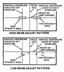
(7)
Switch on the headlamps on full beam. The
shaded area as shown indicates the high
intensity zone of the high beam.
(8)
Turn top adjusting screw on headlamp for
vertical adjustment, side screw for horizontal
adjustment.
(9)
Switch headlamps to low beam. The shaded area
indicates the high intensity zone of the low
beam.
(10)
Make further adjustments as required, but be
aware any further adjustment will alter high
beam pattern. Also low beam should never be
above the height of the lamp centers and should
always be to the right of the center line of the
lamp.
NOTE
If the truck is to be operated on the left hand side of
the road, e.g. England, the low beam should be offset
to the left of the lamp center line.
4-446/(4-447 Blank)
|