|
| |
TM 5-4210-220-12
4-23. FUEL SYSTEM AND AIR INTAKE - Continued
(2)
Clean pump body with dry cleaning solvent (item 10, Appendix E)
(2)
Spin driveshaft and check it operates freely and smoothly
(3)
If the pump is damaged or has failed in service, refer to REPAIR procedures following
INSTALLATION
NOTE
The pump must be installed with the inlet opening (marked "LH IN") next to the balance weight cover. The inlet
and outlet openings must be vertical, the inlet being the lower opening.
(1)
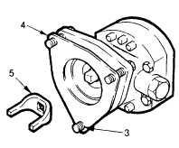
Place anew pump gasket (4) against the mounting flange and hold in place with the protruding ends of the
three mounting bolts (3).
(2)
Place the drive coupling fork (5) on the square end of the shaft.
(3)
Place the fuel pump against the governor housing. Ensure the drive coupling fork registers with the slots in
the drive disc.
(4)
Secure the pump to the governor housing with the three bolts and tighten to 10 ft lb (14 Nm).
(5)
Connect the fuel inlet line to the inlet elbow.
(6)
From the cab, press the fuel priming switch. This starts the priming pump. Continue priming until fuel
spills from the engine fuel pump outlet elbow.
(7)
Connect the fuel outlet line to the outlet elbow.
(8)
Run the engine and check fuel pump for leaks. If any leaks occur, tighten the connections only enough to
stop the leak.
REPAIR
(1)
The pump can only be repaired if it is removed from the truck.
(2)
Drain all fuel from pump by rotating and shaking.
(3)
Mount fuel pump in holding fixture J1508-10. The fixture should be mounted in a vise.
(4)
Remove fuel inlet and outlet elbows from the pump cover.
4-401
|