|
| |
TM 5-4210-220-12
4-22. AIR SYSTEM - Continued
(2)
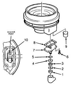
Remove nut 1), lockwasher (2), nut (3),
flatwasher (4), and O-ring (5). Discard O-
ring.
(3)
Remove four screws (6) and cover (7).
(4)
Remove and discard gasket (8).
(5)
Remove and retain spacer (9).
(6)
Cut uninsulated thermostat wire at Point
B. Remove and discard thermostat and
terminal assembly (10).
(7)
Clean remaining wire attached to heater
terminal.
(8)
Clean thermostat "pocket" in end cover.
(9)
Cut uninsulated lead of new thermostat
(10) at point A.
(10)
Install thermostat in end cover "pocket" and position uninsulated leads next to each other.
(11)
Using a soldering heat sink, clamp uninsulated leads at Point B and solder leads with straight rosin core
solder. DO NOT USE ACID CORE SOLDER. Clean excess solder off end cover.
(12)
Install thermostat terminal in cover (7).
(13)
Install O-ring (5), washer (4), nut (3), lockwasher (2), and nut (1). Torque nuts to 24 in. lb (2.7 Nm).
(14)
Install spacer (9) over thermostat (10).
(15)
Install gasket (8) and cover (7) Secure cover to end cover using screws (6). Torque to 36 in. lb (4.1 Nm)
(16)
Test thermostat as follows.
(a)
At a temperature above 85 deg. F (29 deg. C) check resistance between thermostat terminal (1)
and end cover (10). Resistance should be 200,000 ohms or greater, if not, check for solder "path"
short.
(b)
Chill entire end cover assembly to 35 deg. F (1.5 deg. C) or below and check resistance again.
Resistance should be 2 - 15 ohms.
(17) Install end cover in drier as detailed in End Cover Repair, steps 7 thru 10, preceding.
(18) Install and test air drier as detailed in INSTALLATION preceding.
4-385
|