|
| |
TM 5-4210-220-12
4-22. AIR SYSTEM - Continued
4-22.6 Air Regulators - Continued
REPAIR
NOT
Valve must be removed from truck
for
repair.
See
REMOVAL
preceding.
(1)
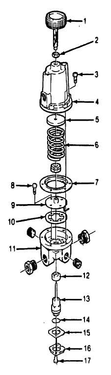
Remove screws (17) from base of valve.
Lift off retaining cap (16) and plate (15).
(2)
Pull exposed hexagon brass portion out of
valve. Whole inner valve assembly is
attached to this piece.
(3)
Remove six screws (3) and lift bonnet
assembly from valve.
(4)
Remove screws (8). Lift out jet tube
assembly (9). Be careful not to bend the jet
tube.
(5)
Remove cork gasket (10).
(6)
Push downwards on the seat ring (12).
Force should be applied to the brass portion
of the seat ring visible from the top of the
regulator. Force ring out of bottom of
regulator.
(7)
Discard seat ring (12) seal ring (14), cork
gasket (10), inner valve assembly (13) and
diaphragm (7).
(8)
Clean all remaining components. Be sure
all foreign matter is removed.
(9)
Coat the outside of the new seat ring (12)
with petroleum jelly (item 21 Appendix E).
Place in body, brass side first. Press into
place being careful not to damage rubber
seal.
(10) Placecork gasket (10) into body (11).
(11)
Install jet tube assembly over gasket, aline
sides and install screws (8) Tighten firmly.
Be sure jet tube is positioned into outlet port
of regulator.
(12) Insert new inner valve assembly (13) into
valve body. Be sure screen is centrally
located in the groove on the topside of the
valve body.
4-356
|