|
| |
TM 5-4210-220-12
4-18. PUMP, PIPING, AND VALVES - Continued
REMOVAL
(1) Close roof turret ball valve (1).
(2) Remove victaulic coupling (2), see para. 4-18.3.
(3) Remove the four locknuts (11) and two studs (12, 13) that retain the handle assembly (10) to the turret.
Discard locknuts.
(4) Pull fast pin (14) from handle lock (15) and remove handle assembly (10).
(5) Loosen gear clamp and remove hose (3) from automatic drain valve (4).
(6) Remove automatic drain valve (4), fittings, and street elbow from base of roof turret.
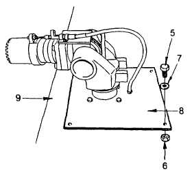
(7) Remove the four capscrews (5), washers
(7), and locknuts (6) that retain the turret
mounting plate (8) to the cab roof (9).
(8) Using a screwdriver, break the sealant
bond between the roof (9) and the
mounting plate (8).
(9) Carefully maneuver the roof turret and
mounting plate assembly out of truck. It
may be necessary to turn roof turret to
allow the control handle and bracket to
clear the roof turret hole.
INSTALLATION
(1) Clean old sealant from the roof (9) and the mounting plate (8).
(2) Apply a continuous bead of sealant (item 25, Appendix E) to the perimeter of roof turret hole.
(3) Lift roof turret assembly onto truck roof and carefully lower it into plate. It will be necessary to turn roof
turret to allow the control handle and bracket to clear the roof turret hole.
(4) Align mounting holes with minimum lateral movement. Apply sealant (item 25, Appendix E) to capscrew
shoulders (5), washers (7) and install them into the mounting holes. Install locknuts (6) and tighten to 28
ft lb (38 Nm).
(5) Apply pipe sealant (item 22, Appendix E) to threads of fittings and assemble as shown.
(6) Install drain hose (3) onto barbed nipple. Install gear clamp and tighten firmly.
(7) Install victaulic coupling (2), see para. 4-18.3.
(8) Lift the handle assembly (10) up to turret and align the mounting holes.
(9) Install studs (12, 13) and locknuts (11) and tighten to 17 ft lb (23 Nm).
4-261
|