|
| |
TM 5-4210-220-12
4-18. PUMP, PIPING, AND VALVES - Continued
4-18.3 Victaulic Couplings.
This task covers Replacement
TOOLS
MATERIALS/PARTS
Tool Kit, General Mechanic, Automotive,
21, Appendix E Petroleum Jelly
NSN 5180-00-177-7033
75-E-1.5" Victaulic Seal
75-E-2.5" Victaulic Seal
EQUIPMENT CONDITION
75-E-4.0" Victaulic Seal
Main Engine Shutdown (see para. 2-10)
75-E-5.0" Victaulic Seal
APU Shutdown (see para. 2-12)
Batteries Disconnected (see para. 4-24)
All Piping Drained
NOTE
To replace some couplings, it may be necessary to remove the heat shields (see para. 4-11) or
to drain the water tank (see Chapter 2).
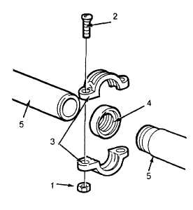
REPLACEMENT
(1)
Remove the nuts (1) and capscrews (2) retaining the clamp halves (3) together.
(2)
Separate the clamp halves (3) and remove. It may be necessary to break the seal between the gasket
(4) and the clamp halves (3) using a small hammer.
(3)
Remove gasket (4) from pipe and discard.
(4)
Clean the pipe ends (5) and inspect for damage such as
indentations, roll marks or projections that might cause
the gasket (4) to leak Replace defective piping as
required.
(5)
Inspect clamp halves (3) for cracks or dents.
(6)
Using petroleum jelly (item 21, Appendix E), uniformly
lubricate the entire gasket (4) and the pipe ends (5).
(7)
Install new gasket (4) onto one pipe.
(8)
Maneuver the second pipe and slide the gasket (4) onto
it. Center the gasket over both pipes (5).
(9)
Position the clamp halves (3) over the pipes (5) and
gasket (4) Ensure the clamp lips lay in the rolled
grooves.
(10)
Install the capscrews (2) and nuts (11) and tighten as
indicated
4-224
|