|
| |
TM 5-4210-220-12
4-17. PUMP DRIVE AND PTO - Continued
INSTALLATION
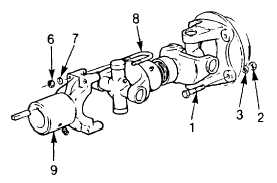
(1) Compress the reducer gear to pump drive shaft to the shortest possible length.
(2) Raise the reducer gear to pump drive shaft into position and support using mechanics wire.
(3) Ensure the bearing caps (11) of the universal joint are fully seated into the end yoke (9) of the reducer gear.
(4) Install the U-bolts (8). Using a hammer, lightly tap U-bolts until they contact the bearing cap.
(5) Apply threadlock liquid (item 29, Appendix E) to U-bolt threads. Install the lockwashers (7) and nuts (6)
Tighten nuts to 32 ft lb (43 Nm).
(6) Align the holes of the flanged yoke (4) with
the holes in the pump drive flange (5).
(7) Install the capscrews (1), lockwashers (3),
and nuts (2). Apply threadlock liquid (item
29, Appendix E) to capscrews (1). Tighten
nuts to 110 ft lb (150 Nm).
(8) Remove mechanics wire used as a support
(9) Lubricate both universal joints, until grease
(Item 16, Appendix E) is expelled from all
bearing cap seals
(10) Lubricate slip joint until grease (item 16,
Appendix E) is expelled from welch plug.
Cover welch plug with finger and continue
lubricating until grease is expelled from dust
cap.
4-211
|