|
| |
TM 5-4210-220-12
4-15. AUXILIARY POWER UNIT - Continued
(19)
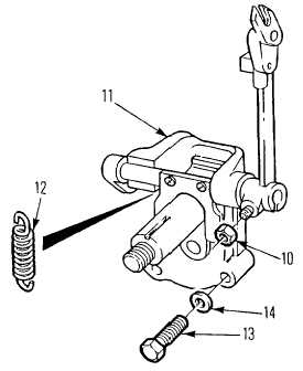
Install pump assembly in block ensuring
back plate is alined with spindles.
(20)
Secure assembly with four screws (13)
and washers (14).
(21)
Attach spring (12) to governor input shaft.
(22)
Install injector pump fuel rack actuator to
cover and to fuel rack mechanism.
(23)
Install drive key in governor drive shaft
and push drive gear on shaft.
(24)
Install gear nut and washer and torque to
25 ft lb (34 Nm).
(25)
Set up governor as detailed in para.
4-15. 14.
(26)
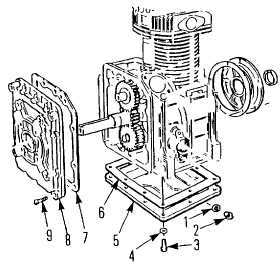
Install crankcase cover (8) using new
gasket(s) (7). Ensure it is the same
thickness as the one removed. Be careful
not to damage oil seal as it is pushed
along crankshaft.
(27)
Fasten crankcase cover using machine
screws (9) Ensure oil breather tube is
connected with bottom left hand screw.
(28)
Install oil drain plug (2) and washer (1) in
pan and install pan (5) on crankcase with
new gasket (6) Tighten capscrews to 25 ft
lb (35 Nm).
(29)
Install engine on base as detailed in para.
4-15.1 ASSEMBLY.
(30)
Install engine in truck as detailed in para.
4-15.1 INSTALLATION
4-187
|