|
| |
TM 5-4210-220-12
4-13 PUMP BODY - Continued
4-13.1 Structural Control Panel - Continued
(14)
Pull cable free of APU compartment.
(15)
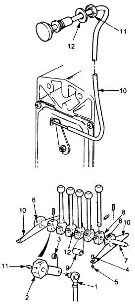
Unscrew nut (11) and pull cable out of
control panel.
(16)
Install new control cable (10) and attach
to panel using new nut (11) and washer
(12). Tighten nut firmly.
(17)
Route cable into the APU compartment.
(18)
Attach cable to APU fuel shut off lever.
(19
Install APU as detailed in para. 4-15.1.
(20)
Start APU, see para. 2-12 and be sure
engine operates correctly.
h.
Valve Lever Repair.
NOTE
Control
panel
removed
from
console.
See
REMOVAL
procedure preceding. The valve
control levers are assembled in
two banks which are identical
except for the number of levers.
The repair procedure is the same
for both banks.
(1)
Disassemble tie rod linkages and lever
locks. For each linkage, remove nut (3)
and pull tie rod end (1) free of lever lock
(2).
(2)
Remove four screws (4) and nuts (5)
attaching lever bank to pump body
console.
(3)
Remove lever bank from console.
(4) Loosen two setscrews (6) and remove
shaft (7).
(5)
Inspect lever locks (8). The bore in each lock should be smooth and well lubricated.
(6)
Inspect shaft (7). It must be straight and the surface smooth. Minor surface damage and scratches may
be removed using emery cloth (Item 12 or 13, Appendix E).
(7)
Install shaft locks (8) and spacers (12) on shaft (7) using new and/or old parts as required.
(8) Install control brackets (13) to shaft and tighten setscrews (6).
4-126
|