|
| |
TM 5-4210-220-12
1-9. LOCATION AND DESCRIPTION OF MAJOR COMPONENTS. - Continued
e.
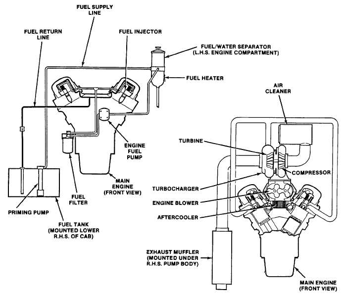
Fuel, Air Intake, and Exhaust Systems.
(1)
The fuel system comprises a 45 gallon fuel tank, 12-volt electric priming pump, fuel/water separator,
engine fuel pump, fuel filter, and supply and return lines between tank and engine, (see fig. 1-8). The fuel/water
separator is equipped with a heater element for cold weather operation. Both the fuel/water separator and the fuel filter
have replaceable filter elements.
(2)
The air intake system consists of the air filter, turbocharger compressor, engine blower, and aftercooler.
The exhaust system consists of exhaust piping, turbocharger turbine, and muffler. The air cleaner is mounted above the
engine and connected with a flexible elbow to the turbocharger. The exhaust pipe is flange mounted to the turbocharger.
The muffler is mounted to the frame with rubber bushings and hanger brackets.
Figure 1-8. Fuel, Air Intake, And Exhaust Systems
1-9
|