|
| |
TM 5-4210-220-12
1-9. LOCATION AND DESCRIPTION OF MAJOR COMPONENTS. - Continued
b.
Cab and Body. - Continued
(6)
The fire wall dividing the cab also forms part of the engine compartment. The left and right sides of this
compartment have large removable panels to provide service access. The top of the compartment is provided with an
engine air intake opening. The pump body encloses the fire pump, piping, and control valves for the firefighting system.
To access this equipment, the front face of the body is provided with a large removable panel and the side faces with
smaller access doors. A control panel for structural firefighting is located at the top front of the body. Refer to Chapter 2
for operating details of the control levers and indicators. The lower front part of the pump body consists of two steps on
each side and a catwalk across the truck. The steps and catwalk provide access to the rear crew seats and the structural
control panel. The steps and catwalk are clad with non-skid aluminum sheeting.
(7)
The rear engine compartment panel is provided with vent holes. During winter operation, warm air from
the engine, vented through these holes, keeps the catwalk free of ice.
(8)
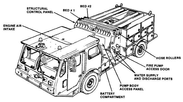
Draft, hydrant, and water discharge ports are located on both the left and right side of the pump body, (see
fig. 1-4). The top of the body contains two cross-lay hose beds. These beds are equipped with vertical and horizontal
aluminum hose rollers at both ends to ease hose play-out from either side of the truck. The beds accommodate 1-1/2
inch fire hose. The beds are identified as BED #1 (front bed) and BED #2 (aft bed). A hinged step is attached to each
side of the body to provide access to these hose beds.
Figure 1-4 Cab and Pump Body Components (Continued)
(9)
The hose body houses the water and foam tanks and contains storage compartments for auxiliary
equipment, (see fig. 1-5). The body structure, is made of aluminum.
(10)
Two large storage compartments are provided on the upper left hand side of the rear body. These
compartments are equipped with top hinged doors and collapsible gas cylinders to support the doors in the fully open
position. All other doors are fitted with spring-type hatch holders.
1-5
|