|
| |
TM 5-4210-218-13&P
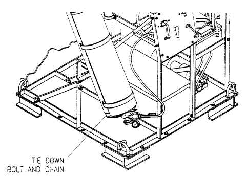
i. Use the tilt rack to invert the Halon cylinder. Connect the snap end of the tilt rack lock down chain to the eyebolt to hold
the tilt rack in the inverted position.
Figure 2-6. Halon Cylinder Inversion.
2-7. SYSTEM LEAK TEST.
a.
Insure that all valves are in the closed or OFF position.
b.
Disconnect the nitrogen hose from the elbow on the HALON / nitrogen valve.
c.
Attach nitrogen hose to the test adapter. The test adapter is located in the tool box and consists of a quick
disconnect plug and a reducing connector to fit the nitrogen hose.
d.
Connect the test adapter to the Halon hose.
e.
Set the outlet pressure gauge on the nitrogen pressure regulator to 400 psi by turning the adjustment screw
counterclockwise.
f.
Open the nitrogen supply cylinder valve.
CAUTION
If inlet pressure gauge on the control panel reading exceeds 500 psi. close
nitrogen supply cylinder valve, release pressure from the system by opening the
extinguisher hose ball valve and readjust the nitrogen pressure regulator outlet
pressure gauge. Repeat step f.
2-15
|