|
| |
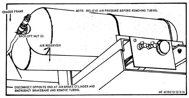
Figure 3-16. Air Tank tubing and fittings, removal and installation.
Section Xl. ELECTRICAL SYSTEM
3-48. General
The electrical system consists of two spotlights, one
mounted on each of the windshield posts, two rear
spotlights mounted on the rear of the fire truck, and
electrical siren mounted on the left front fender, rotating
warning light mounted on the top of the cab. These
lights are waterproof, sealed-beam-type lamps. A
flasher assembly mounted behind the cab instrument
panel functions to interrupt the circuit to directional light
assemblies. A dome light mounted above the left side
control panel furnished illumination for pump operating
controls. A temperature warning light, oil pressure
warning light, and two panel lights are mounted in the
instrument panel on the left side. Two underhood lights
mounted on each side of the front of the radiator furnish
illumination for the engine. Two solenoid relays and
motors, one mounted on each hose reel assembly and
one motor solenoid and motor mounted on the priming
pump serve to furnish power for the priming pump and
hose reels! There are two battery charging receptacles
located at the rear of the vehicle. Two
12 volt batteries and their cable assemblies supply
power to the unit. The temperature and oil pressure
sending units are mounted on the engine. Refer to T M
9-2320-209-10 for the chassis and engine electrical
components.
3-49. Wiring
a.
General. When testing, repairing, or -replacing
the wiring, refer to wiring diagram (fig- 1-3).
b.
Testing. Test a wire for continuity by
disconnecting each end from the components to which it
is connected. Touch' the test probes of a multimeter to
each end of the wire. If continuity is not indicated, the
wire is defective and must be repaired or replaced.
c.
Repair. Shave the insulation on the wire at both
ends of the break and twist the bare wires together and
solder the Connection. Cover the- repaired' breaks with
electrical tape and friction tape. If a terminal breaks off
a wire, replace it, using a like terminal.
d.
Replacement. Replace a wire by disconnecting
it from the component or components and remove the
wire. Install a new wire and attach it to the outside of
the-wiring harness.
3-27
|