 |
|||
|
|
|||
|
Page Title:
Testing of Radio Interference Suppression Components |
|
||
| ||||||||||
|
|
 1
Screw, machine, 10-32 x 1/4 in.
1
Screw, machine, 8-32 x 1/4 in. (2 rqr)
1
Screw, cap, 3/8-16 x 1 in.
2
Washer, lock, ET, 1/4 in.
2
Capacitor, 25 mfd-100 vdc-20 amp
2
Washer, lock, ET, 3/8 in.
3
Screw, machine, 10 32 x 1/4 in.
B-Beacon warning light capacitor
3
Ground strap (2 rqr)
4
Washer, lock, ET, 1/4 in.
1
Screw, machine, 8-32 x 1/4 in. (2 rqr)
4
Nut, 3/8-16
5
Capacitor, 1.0-50v
2
Capacitor, 0.1-100 dc
D-Hose reel to hose reel motor ground strap
A
Turn signal flasher capacitor
C-Siren-light flasher capacitor
Figure 21-Continued.
that are identical. Capacitors must be the same size
and have the same rating as the parts being replaced. It
is essential that a good-metal-to-metal contact is
achieved to maintain proper radio interference
suppression. To correct faulty suppression, substitute
new interference suppression components until the
faulty components are discovered.
Remove the
capacitors and ground straps in the numerical sequence
as illustrated on figure 21.
b. Secondary Suppression Component. Remove
tooth-type lockwashers. If proper suppression is to be
obtained, it is necessary that good metal-to-metal
contact is made by tightening the mounting hardware
employing tooth-type lockwashers.
54.
Testing of Radio Interference Suppression
Components
Test the capacitors for leaks and shorts on a
capacitor tester; replace defective capacitors. If test
equipment is not available and interference is indicated,
isolate the cause of interference by the trial-and-error
method of replacing each capacitor in turn until the
cause of interference is located and eliminated.
1
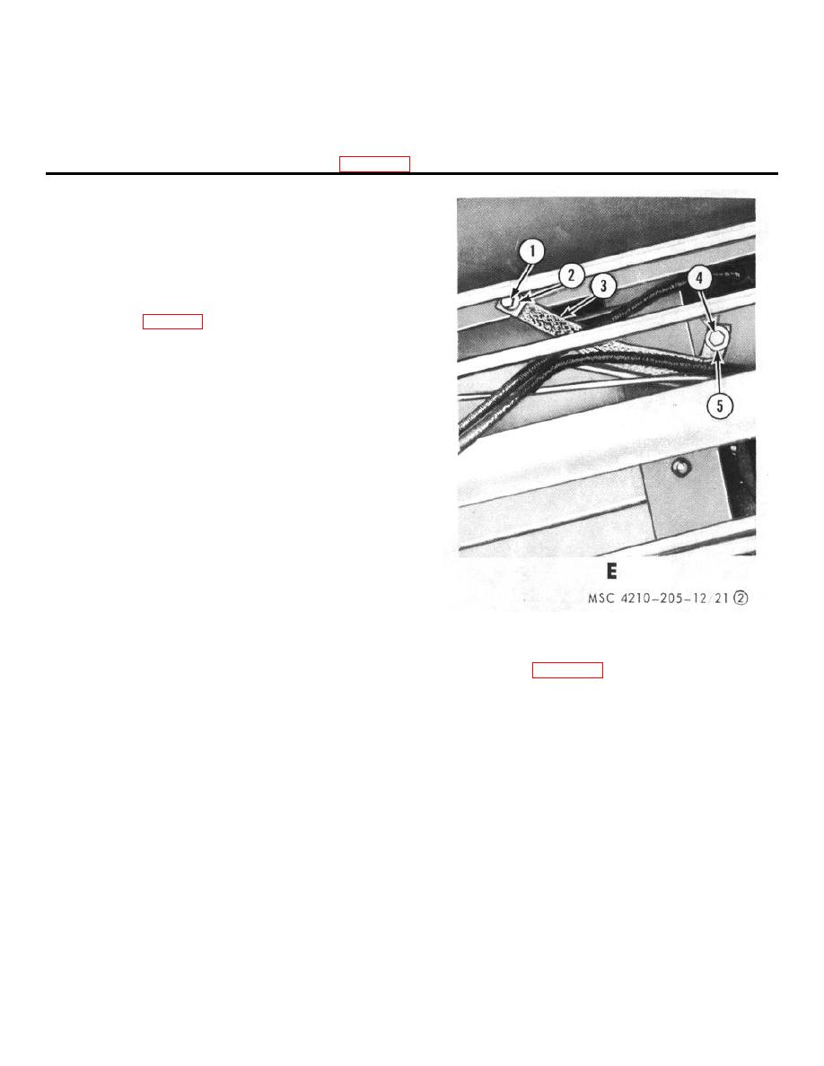
Screw, cap, 7 7/16-20 x 1 in.
4
Screw, cap, 7/16-20 x 1 in.
2
Washer, flat, 7/16 in.
5
Washer, flat 7/16 in.
3
Ground strap (2 rqr)
E - Pump compartment to chassis frame ground strap
Figure 21--Continued.
Section VII. RETAINERS, STEPS, TOOL BOX DOOR, GUARDS, HOSE BED ASSEMBLIES, AND LADDER
SUPPORT ASSEMBLIES
brackets are mounted on the rear step. Folding steps
55. General
are mounted at the front of the hose reel compartments
and at the rear of the fire truck. A handrail is mounted
The hose retainer mounted on the right rear of the fire
on the rear of the fire truck and splash guards are
truck provides a means of locking the hoses, inside the
mounted on each side of the fire truck below the
hose compartment. A retainer and bracket provides a
instrument panels. The tool box door is mounted to the
means for mounting two foam applicator tubes. Two
rear step between the fire extinguisher brackets. The
shovel buckets are located on the left rear of the fire
hose bed partition is located on top of the fire truck
truck. The ladder brackets are mounted on the top front
water tank and divides the hose compartment into
of the left side compartments. Two fire extinguishers
TAGO 6839A
44
|
|
Privacy Statement - Press Release - Copyright Information. - Contact Us |
