 |
|||
|
|
|||
|
Page Title:
Figure 71.34. Space heating system. |
|
||
| ||||||||||
|
|
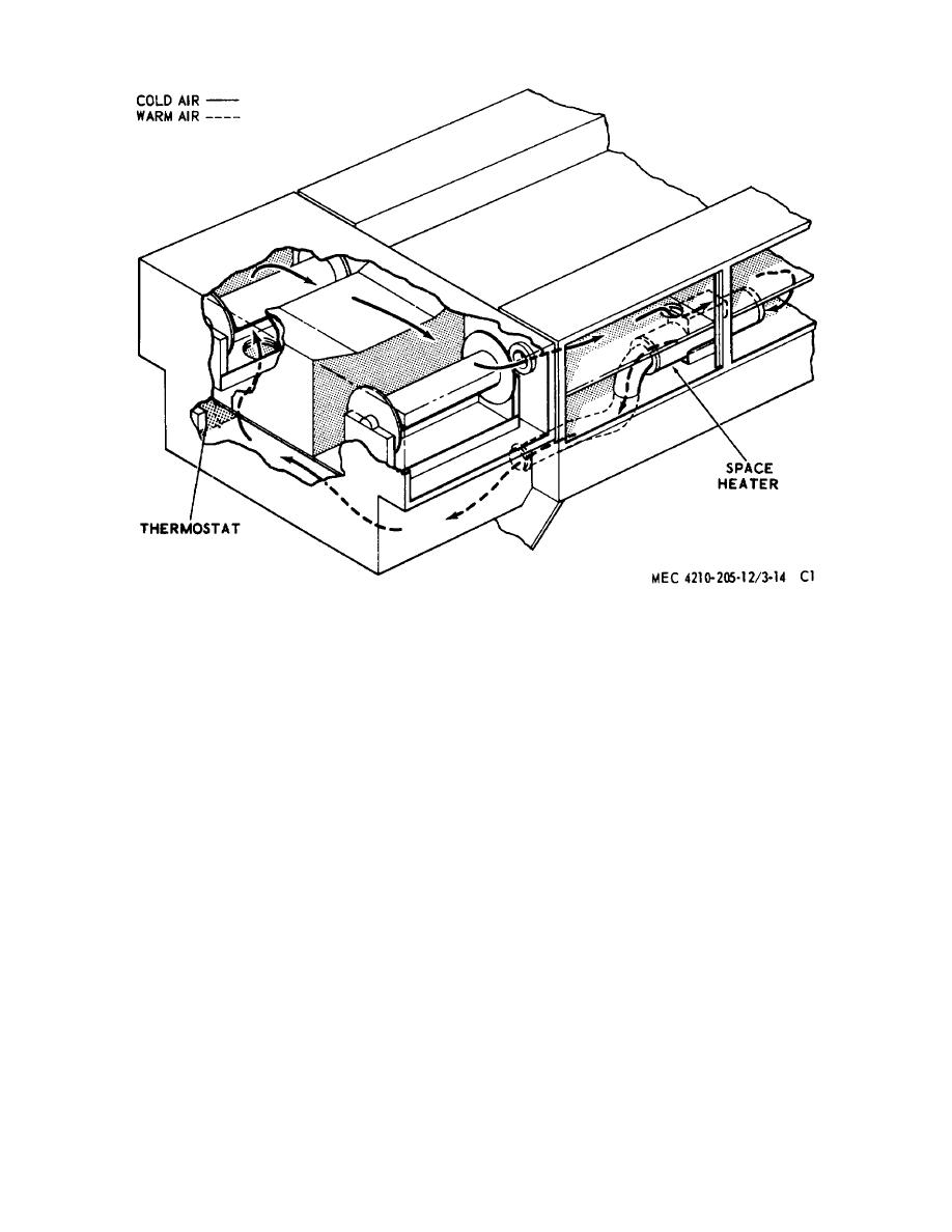 Figure 71.34. Space heating system.
Remove the motor (47) from the motor
e.
Blower Motor Test. Reassemble the blower
clamp (51).
assembly to test the motors. Connect a 24 vdc power
supply to the assembly and operate the motor. Check
c.
Casing Disassembly.
the motor speed with a stroboscope. Minimum speed
(1) Remove the spark plug assembly (6),
allowed is: 5,000 rpm, circulating motor; 6,500 rpm,
spark plug seal washer (7), and spark plug
combustion motor.
seal (8) from the burner.
f.
Blower, Burner and Combustion Chamber
(2) Remove the four screws (79) attaching
Reassembly.
the heater mounting base assembly (80)
(1) To assemble the blower, burner, and
to the casing; remove the base assembly.
combustion chamber, insert the burner
(3) Remove the seals (81) from the
assembly (40, fig.
71.35) into the
combustion air ports, and the five screws
combustion chamber. Align the burner
(24) fastening the casing assembly (1).
brackets with the screw holes in the
Spread the casing apart at the joint and
combustion chamber sides and fasten in
remove the combustion air blower
place with two washers (31) and screws
assembly (63), burner (40), and
(32), being careful to hold the burner in
combustion chamber (26) as an
place against the throat of the combustion
assembly. Withdraw the wires through
chamber.
the grommets (23) and (9) in the casing
during the removal.
d.
Contact Plate. Refer to paragraph 194g.
AGO 5667A
37
|
|
Privacy Statement - Press Release - Copyright Information. - Contact Us |
