 |
|||
|
|
|||
|
Page Title:
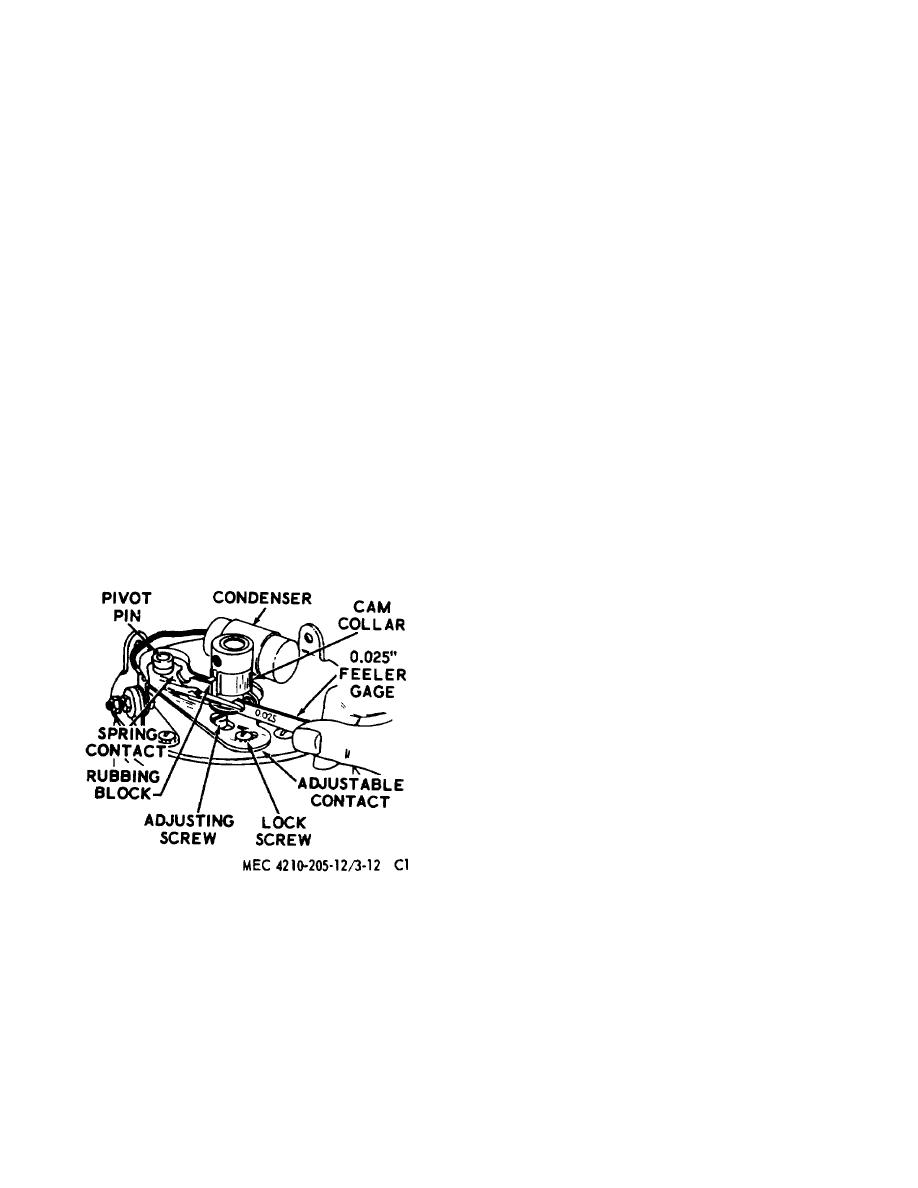
Figure 71.32. Adjusting the contact plate point gap |
|
||
| ||||||||||
|
|
 and capacitor.
(b) If the gap needs adjusting, loosen the
adjustable contact mounting screw
(b) Disengage the contact spring from
and position the stationary contact to
the terminal screw (69), and lift the
correct the contact gap. Tighten the
movable (top) contact from the pivot
mounting screw.
pin. Remove the screw (47) and
(4) Contact Plate Reassembly. Install contact
washer (46), and then remove the
plate on the blower motor as instructed in h
adjustable (bottom) contact from the
pivot pin.
(6) below.
Note
h.
Blower, Burner, and Combustion Chamber
Be sure to place the rubbing block of
Reassembly.
the movable contact between the two
(1) To assemble the blower, burner, and the
teeth on the brass cam collar.
combustion chamber, position the gasket
(c)
Secure the capacitor to the
(29, fig. 71.31) on the preheater (30), and
contact plate with the capacitor bracket
screw the heater onto the burner assembly
(59), screw (57) and washer (58). Engage
(28).
the capacitor lead wire with the terminal
(2) Insert the post insulator (34) into the
between the contact spring and brass
opening on the combustion chamber.
washer. Tighten the terminal nuts (40).
Attach the connector band (35) to the post
(3)
Contact Plate Gap Adjustment (fig. 71.32).
insulator with a brass screw (39) inserted
(a) With the cam and contact plate
from inside the combustion chamber.
assembled to the motor, rotate the motor
Position the insulator washer (33), flat
shaft until the movable contact is at the
washer (32), and control head lead on the
high point of the cam. Make sure the
screw; secure with a nut (20).
rubbing block of the movable contact is
(3) Insert the burner assembly into the
between the teeth of the cam collar. At
combustion chamber (1). Align the burner
this position, an 0.025-in. feeler gage
brackets with the screw holes in the
should just pass between the contacts
combustion chamber sides, and fasten with
two screws (24) and washers (23), holding
the burner in place against the throat of the
combustion chamber.
Secure the
connector band (35) to the terminal of the
preheater (30) with the preheater nut (36).
(4) Install the gasket (8), union seal (7), union
seal washer (6), and union (5) on burner
fuel feed connector.
(5) Apply several drops of light oil on the cam
collar (43). Position the cam collar and the
cam bushing (44) on the contact cam (67).
Align the holes of the contact cam and the
cam bushing, and install the setscrew (56)
just far enough to hold the parts together.
Position the cam assembly on the motor
shaft so that the setscrew is aligned with
the flat on the motor shaft, and tighten the
setscrew. Make sure that some clearance
exists
Figure 71.32. Adjusting the contact plate
point gap.
AGO 5667A
34
|
|
Privacy Statement - Press Release - Copyright Information. - Contact Us |
