|
| |
TM 10-4210-235-13
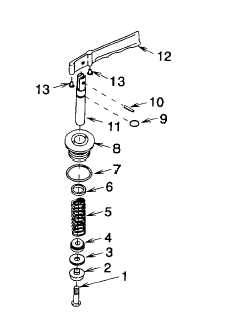
Figure 5-2. Valve Assembly
c.
Assembly
(1)
Install drive buttons (13) (fig. 5-2) into lever (12).
(2)
Secure valve stem (11) to lever (12) using new spring pin (10).
(3)
Install new preformed packing (9) onto valve stem (11).
(4)
Install new preformed packing (7) onto rear seal bushing (8).
(5)
Slide rear seal bushing (8), new rod wiper (6), spring (5), spring retainer (4), new gasket (3), and valve seal
washer (5) onto valve stem (11). Secure using screw (1) and tighten to 24 in. lb (3 Nm).
(6)
Install rear seal bushing (13) (fig. 5-1) into valve body (11) and tighten.
(7)
Install valve handle (10) and align with valve body (11) matching scribe line made during disassembly.
Install four screws (12).
(8)
Install new preformed packing (9) onto forward valve seat (8).
(9)
Install forward valve seat (8) onto valve body (11) and tighten.
(10)
Install sleeve (7), nozzle tip (6), and new gasket (5) into nozzle (4).
(11)
Install nozzle (4) onto forward valve seat (8) and tighten.
(12)
Wrap antisieze tape around nipple (3) threads and install onto valve body (11). Tighten securely.
(13)
Install tie bar (2) and four screws (1).
(14)
Install nozzles per paragraph 4-14.
5-5
|