|
| |
TM 10-4210-235-13
d.
Assembly
(1) Wrap antisieze tape around threaded ends of nipples (51) (fig. 4-20) and (49) and male ends of reducer
(47) and swivel fitting (13) Connect nipple (51), valve (50), nipple (49), elbow tee (48), reducer (47), and
swivel fitting (13).
(2)
Wrap antisieze tape around threaded ends of nipples (46), (43), (41), (39), (37) and male ends of pressure
relief valve (44) and swivel fitting (10). Connect nipple (46), elbow tee (45), pressure relief valve (44),
nipple (43), elbow (42), nipple (41), check valve (40) with flow arrow pointed away from nipple (41), nipple
(39), tee fitting (38), swivel fitting (10), nipple (37), and ball valve (14)
CAUTION
If the gas tube is not assembled to the dimensions given, equipment failure can result.
(3)
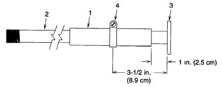
Slip rubber sleeve (1) (fig. 4-21) down onto dip tube (2) 1 inch (2. 5 centimeters) away from end plate (3).
Secure with hose clamp (4) positioned 3 1/2 inches (8 9 centimeters) away from end plate (3).
Figure 4-21. Gas Tube Assembly Dimensions
(4)
Wrap antisieze tape around threaded end of dip tube (34) (fig. 4-20) and connect to reducer (33).
(5)
Wrap antisieze tape around threaded ends of nipple (31) and male end of reducer (33). Connect reducer
(33), elbow (32), nipple (31), and union (15) half.
(6)
Wrap antisieze tape around threaded ends of nipple (28). Connect reducer (30), elbow (29), nipple (28),
and union (15) half.
(7) Wrap antisieze tape around threaded ends of nipples (25), (23), and (27). Connect union (15) half, nipple
(27), tee fitting (26), nipple (25), elbow (24), nipple (23), and union (15) half.
(8)
Wrap antisieze tape around threaded ends of nipples (22), (20), (18), and (17). Connect nipple (22), elbow
(21), nipple (20), ball valve (19), nipple (18), tee fitting (11), nipple (17), and check valve (16) with flow
arrow pointed toward nipple (17).
(9)
Connect two union (15) halves.
(10) Wrap antisieze tape around one threaded end of hose assembly (12) and connect to ball valve (14).
Connect loose hose assembly (12) end without antisieze tape to swivel fitting (13)
(12)
Wrap antisieze tape around one threaded end of hose assembly (9) and connect to tee fitting (11) Connect
loose hose assembly (9) end without antisieze tape to swivel fitting (10).
(13)
Push new cable (8) end through a new cable sleeve (52) and then loop through hole in valve mounting
bracket (6) Push cable end back into cable sleeve. Secure by crimping sleeve. Repeat for charge valve
mounting bracket (7).
4-49
|