Order this information in Print

Order this information on CD-ROM

Download in PDF Format


Click here to make tpub.com your Home Page

Page Title: Figure 4-13. Hose Roller Assembly Removal
Back | Up | Next

Click here for a printable version

Google


Web
www.tpub.com

Home


Information Categories
.... Administration
Advancement
Aerographer
Automotive
Aviation
Combat
Construction
Diving
Draftsman
Engineering
Electronics
Food and Cooking
Math
Medical
Music
Nuclear Fundamentals
Photography
Religion
USMC
   
Products
  Educational CD-ROM's
Printed Manuals
Downloadable Books


TM 10-4210-235-13 
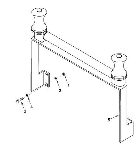
4-18 HOSE ROLLER ASSEMBLY REPLACEMENT. - continued Figure 4-13.  Hose Roller Assembly Removal c. Repair Repair is by replacement of defective or damaged components d. Assembly (See figure 4-14.) (1) Install one pedestal (7), spool (5), bushing (6) screw (4) new lock washer (3), and nut (2). (2) Assemble  tube  (9),  two  bearings  (8),  axle  (10),  and  remaining  pedestal  (7).    Insert  axle  into  pedestal installed on bracket 11 (3)    Install  spool  (5)  and  bushing  (6)  onto  pedestal  (7)  and  secure  to  bracket  (11)  using  screw  (4),  new  lock washer (3), and nut (2) (4) Install two hole plugs (1). 4-36

Privacy Statement - Press Release - Copyright Information. - Contact Us - Support Integrated Publishing

Integrated Publishing, Inc. - A (SDVOSB) Service Disabled Veteran Owned Small Business